 |
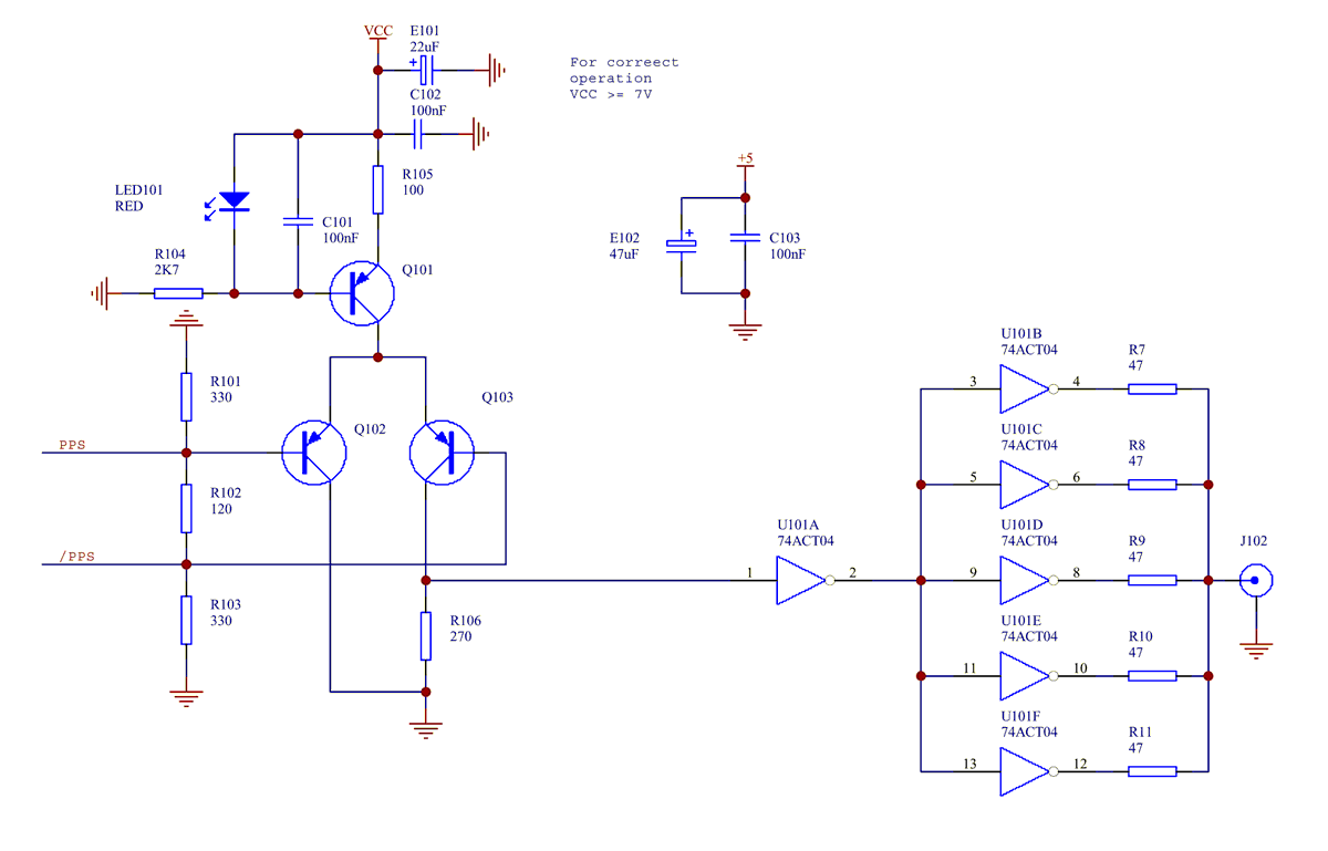
This circuit is intended to translate a 5V differential PECL input to CMOS levels in a 50 ohm load.
The circuit uses a pnp longtailed pair to generate TTL level signal in a 270 ohm load. U101:A CMOS inverter with TTL compatible inputs drives 5 parallel connected CMOS inverters (U101:B .. U101:F) in the same package which in turn drive a load terminated in 50 ohms to ground. Small resistors in series with the inverters driving the 50 ohm load are used to ensure that each inverter output has a similar output current.
The 3 resistor input termination ensures that the open emitter PECL outputs drive a 100 ohm balanced transmission line terminated in its characteristic impedance.A typical use would be to produce a CMOS level PPS pulse in a 50 ohm terminated coax from a differential 5V PECL output from a Z3801.
If a longer duration output pulse is desired a fast CMOS monostable is preferred to a 755 timer as the CMOS monostable propagation delay is smaller and has a lower absolute tempco.
TBC...