When one has 2 sources whose frequencies are equal to better than 1Hz an analog linear phase comparator can be used to determine the frequency difference with a phase comparator system noise level of around 2E-11/Tau to 4E-11/Tau, where Tau is the measurement time.
While simple linear phase comparators like the HP K34-59991A and others have been used for this it is difficult to determine the sign of the phase or frequency difference even when the phase detector has an asymmetric sawtooth characteristic.
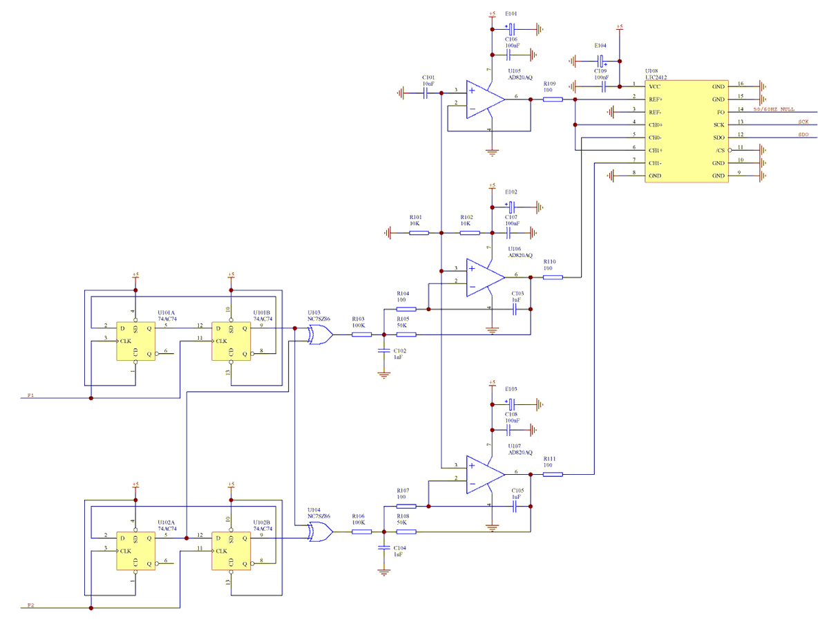
If the frequencies to be compared are first divided by 4 using a pair of 2 bit Johnson counters to produce 2 quadrature phase outputs then a pair of simple exclusive OR (XOR) phase detectors with symmetric triangular phase detection characteristics can be used to unambiguously determine the sign and magnitude of the frequency difference.
If the outputs of the 2 XOR gates are low pass filtered and the filter outputs are measured with high resolution sigma delta ADCs then a resolution of better than 100ppm of the input signal period is readily achieved.
Whilst gate arrays, at first seem attractive, for maximum resolution and to minimise the effects of crosstalk single XOR packages should be used together with 1 dual D flipflop (configured as a divide by 4 Johnson counter) package per input frequency.
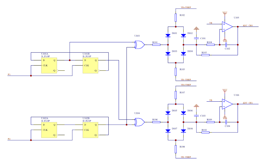
If instead of low pass filtering each XOR gate itself, each XOR gate drives a diode current steering bridge which switches a current source into the summing junction of an inverting low pass active filter (as illustrated in the circuit below) much higher stability and flexibility is possible (circuit can then use CMOS, F-TTL, ECL, LVDS, etc logic).
 |
TBC ..
 |
The above circuit uses CMOS flipflops and exclusive OR gates to implement a linear phase comparator. The LTC2412 ADC reference is derived from the same supply as the CMOS exclusive OR gates. Since phase comparator gain is proportional to the CMOS exclusive OR gate power supply voltage, the ratiometric conversion within the ADC ensures that the ADC output is largely independent of slow power supply voltage variations.
Clock shaping circuits are required (Clock shapers) when comparing low slew rate sinusoidal inputs.
A microprocessor or equivalent is required to interface between the ADC and a data logging PC. For driving a chart recorder a DAC can be used with the effective gain and offset software controlled.
The phase comparator output has a symmetric triangular wave characteristic and has significant nonlinearity at the ends of its range due to the finite slew rate of the exclusive OR gates. The 2 phase comparators operate with a phase offset of 90 degrees so that at least one of the phase comparators operates within the linear region at all times. The maximum usable input frequency is around 50MHz, at higher frequencies the linear range of the comparator becomes too small to be useful. If higher frequencies are to be compared frequency dividers should be used to reduce the comparator input frequency to 50MHz or less.
1) HP K34-5991A Linear Phase Comparator Manual