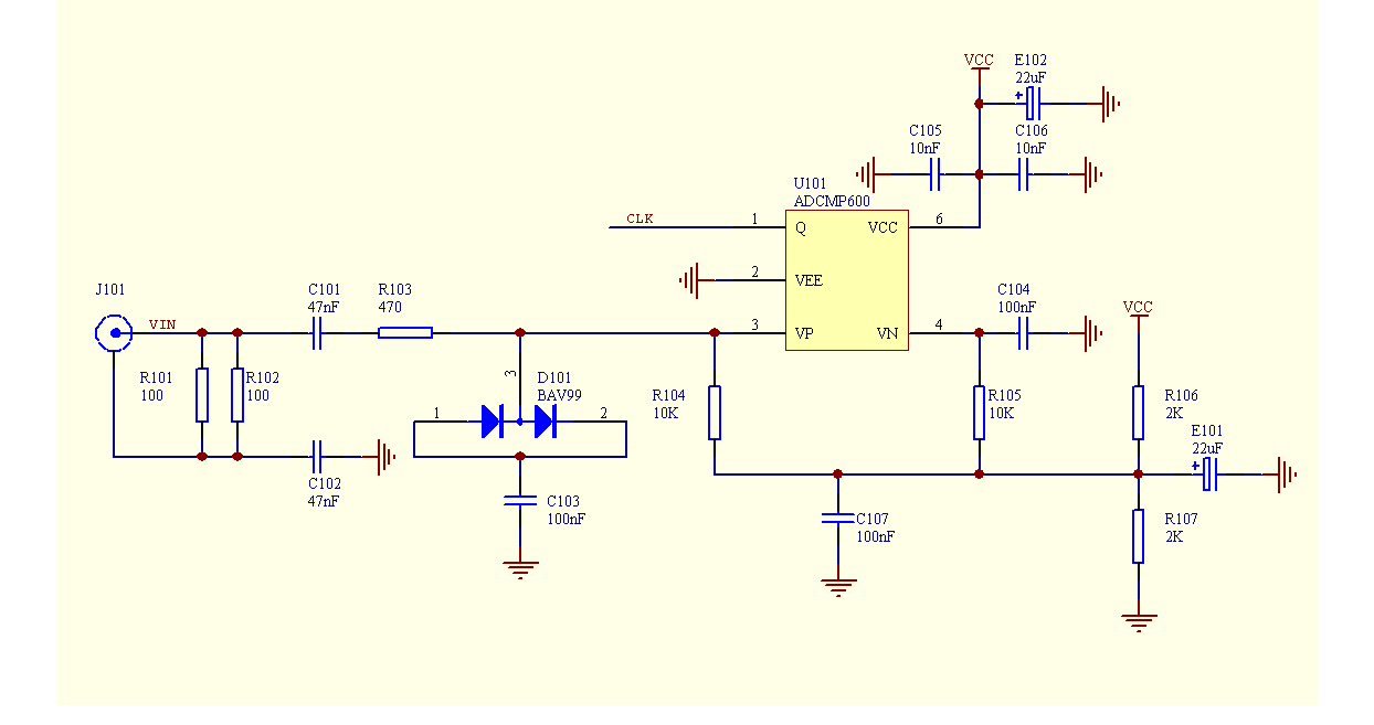
The circuit shown below has a wide bandwidth [<10kHz, > 100MHz]. Input amplitude range is [100mV - 5V]pp.
Originally designed for use in a linear phase detector there are other applications for which it is suitable.
The design is derived from the input clock shaping circuit in the HP K34-5991A. A comparator with a CMOS/TTL compatible output is substituted for the ECL differential amplifiers in the K34-5991A. For higher frequencies either an ECL or LVDS comparator can be used.
 |
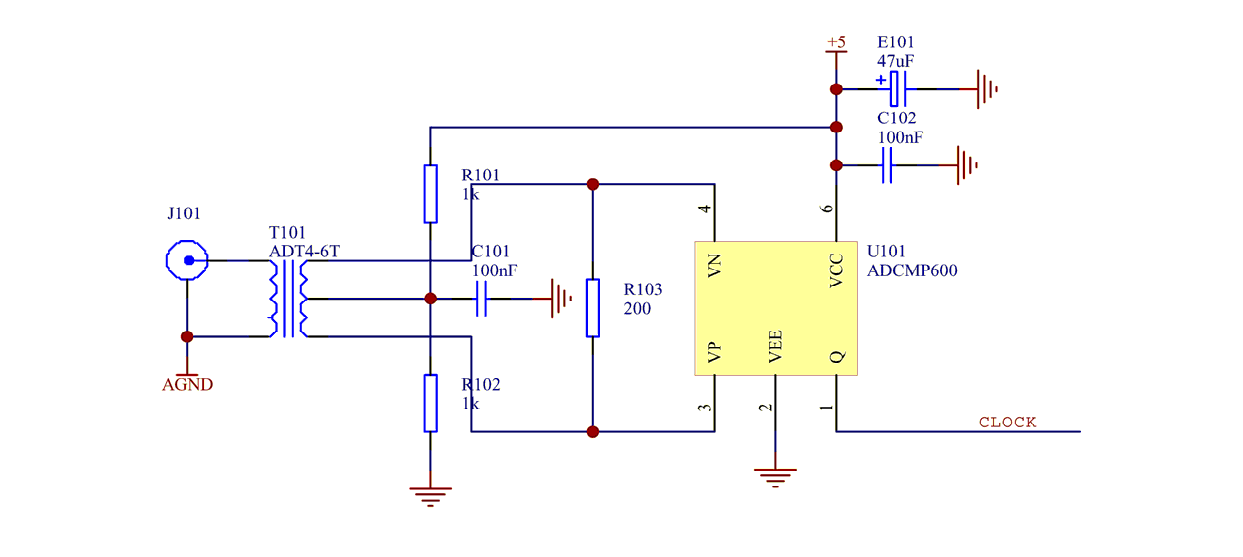
The circuit shown below works over the 0.1MHz to 100MHz frequency range and is intended to produce a TTL/CMOS compatible output when the input amplitude is known and well controlled. As shown the circuit is intended for operation with a +7dB input signal. For lower frequencies other comparators like the AD8561 can be used. For higher frequencies an ECL or LVDS comparator can be used with a suitable transformer.
 |
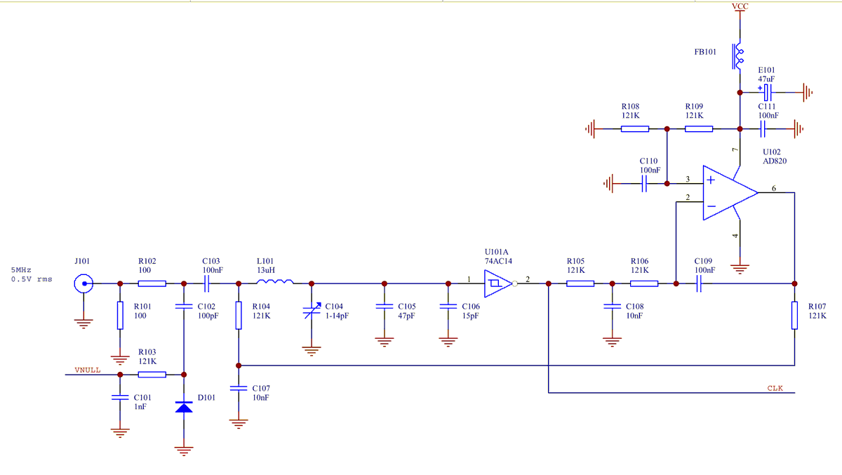
In the circuit below, Schmitt trigger IC U101:A is driven by the sinewave voltage across the low Q tuned tank. The tank is tuned to minimise the dc output from RF detector D101. U102 stabilises the duty cycle of the output of U101:A. This compensates for the part to part variation in the switching thresholds of the 74AC14.
 |
Although a high Q narrow bandpass filter is the obvious approach, using such a filter will severely degrade the phase shift tempco. Its better from the perspective of phase shift stability to use a low pass filter with low phase shift at the signal frequency supplemented by high Q bandstop filters tuned to the frequencies of the harmonics or subharmonics to be eliminated. Such filters can have low phase shift and associated tempco at the signal frequency.